A basic acrobatic tail - Electronics
Compared to the control and mechanical build, the electronics are straightforward enough. To put the simplicity of the circuitry in perspective, it would be trivial to pull out the main controller and hook everything into a radio receiver. Only lights and the safety control loop would be cut out of that design.
Therefore, the only peripherals excluding the PWM for the actuators are the lights (an I2C line into a charlieplex driver and array) and an SPI line for servo monitoring, which will be described shortly.
There is also some protection on the power line — fuses, flyback diodes and low-voltage protection — nothing too non-standard. This iteration was prototyped on protoboard, so it'll be a future commitment to provide PCB layouts that I can share — most of the complexity in the circuitry in this board is really just wiring, and much of that is just hungover from ill-informed design decisions. This block diagram should tell just about all:

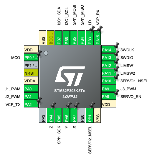
As mentioned in the controls post, there are two computers in the mix: a master controller with lots of IO — in this case an STM32F303 Nucleo (chosen for its FPU) — connected to a programmable ESC powered with a G431.
The aforementioned servo protection circuitry is a straight on-off FET that sits in front of the common servo power line, controlled by the microcontroller which monitors the servo position (via servo pot analog) and its current draw (via shunt resistor). The ESC's software shutoff is a dissipative brake mode when the PWM line falls out of the pulse width range. See here for more details in the code.
The 7.4V protection circuitry consists of a 10A glass fuse and a low-voltage supervisor, which used to be a TLV6713 until it kept breaking for unknown transient-spike kinds of reasons. Still on the lookout for a better-suited supervisor chip.